| S K 0 C T |
Welcome to the home of SK0CT Amateur Radio Club.
Home Introduction, Contact persons HamRadio Resource Pages. Tech.Spec. pages.
SK0CT
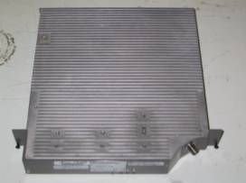
Surplus 23cm power amplifiers
(Only valid for the amplifier type with four amplifier stages and a
final stage with two transistors in parallel)
General
The PA units deliver anything
between 10-20++ Watts output with 10-30mW input on the amateur
frequencies 1260-1300Mhz.
The amount of amplifier gain and power is very much dependent on the
success from re-aligning the striplines of the tuned circuits.
The PA units are set for Class AB, the bias voltages are however
variable with small on-board SMD multiple-turn potentiometers.
A word of caution
There are four separate amplifier stages in series, the final stage is
parallel coupled with two transistors.
Also be aware that all RF
transistors are bipolar and normal precaution is required for these
devices. They contain BeO (poison substance), they burn if too hot, and
they do not survive high SWR and never use DC with higher max.voltages,
measured at the collector, than specified.
When connecting DC voltages, always connect the bias voltage supply
(+5v) before the +23/26V is connected.
When disconnecting DC voltage, always disconnect the bias voltage (+5)
after the +23/26V is disconnected.
Tech.spec bipolar transistor
There are two versions of the amplifier
with different transistors used in the final amplifier stage.
The typical technical specifications, in brief, are:
Stage 1: 20146: 0.03-0.25W input -> 0.4-0.6W output @ 26VDC, 10dB gain
Stage 2: 20046: 1W Pout @ 26VDC, 10.5dB gain
Stage 3: 20074: 14W Pout @ 26VDC, 7dB gain
Stage 4: 20033: 22W Pout @
23VDC, 7.5dB gain / per transistor
Stage 4: 20141: 18 Pout @ 23VDC, 8.5dB gain / per transistor
DC Connector
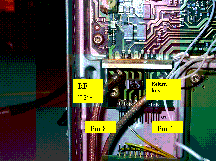
The pin-configuration for the main DC connector:
Pin 1 +5V (Bias supply for all amplifier stages)
Pin 2 (PA protection, optional) not connected
Pin 3 (Temp alarm output, optional) not connected
Pin 4 GND
Pin 5 GND
Pin 6 +26 VDC (for amplifier stages 1-2-3)
Pin 7 +23VDC (for amplifier stage 4)
Pin 8 +23VDC (for amplifier stage 4)
It is possible to connect +23VDC on Pin.6+7+8, the only effect is
slightly decreased total Pout.
To locate Pin 7 & 8: these pins
are both connected to a tantalum SMD capacitor 10uF/30V.
To locate Pin 1: this pin is connected to a tantalum SMD capacitor 2.2uF
/ 20V.
In the middle of the connector, pin 4 and 5 are connected to ground (GND)
RF Input connector
The thin Teflon coax closest to
DC connector Pin 8, with Suhner SMX connector, is used for RF input.
The thin Teflon coax closest to DC connector Pin 1 is used for RF
feedback for returnloss measurements.(optional)
RF output connector
The chassis mounted TNC is RF output, can be replaced for BNC chassis with threads.
Checking
the PA
Valid for a stock amplifier, not re-aligned.
With 30mW input less than 1W output should be observed with DC voltages as specified.
Tuning
Note:
There exist several layouts of the striplines in the final amplifier
stages.
This should be noted when comparing the photos and where the tuning has
been made.
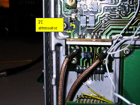
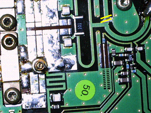
1) between the RF input coax and the first amplifier stage, a PI-attenuator is used, simply bypass it and remove the resistors to ground.
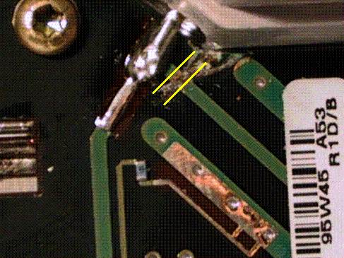
2) Between the RF output connector and the final amplifier stage, cut away the overtone stub
One version of stripline overtone stub to cut away.
Another version of stripline overtone stub to cut away.
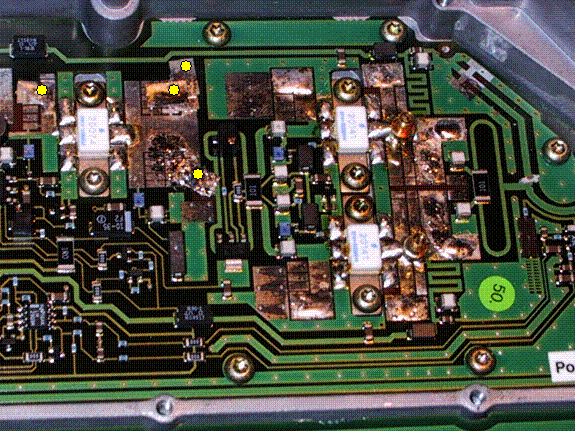
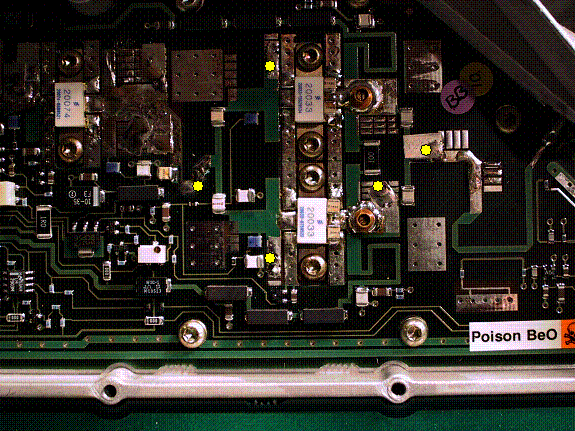
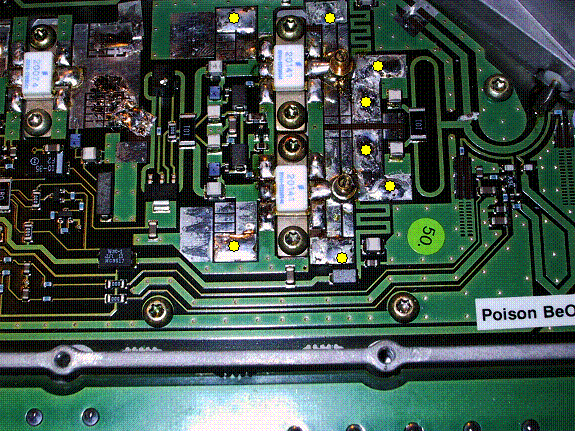
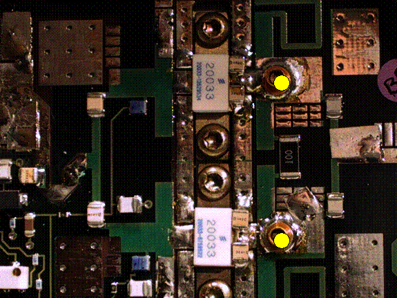
3) Add small copperî flagsî on each position according to the photographs, for each amplifier stage and stripline version used.
First amplifier stage,
common to all stripline versions.
Note: this version used trimmer capacitors, they are optional and may be
used to get that last final tweak of output.
There are no copper flags used for stage 1.
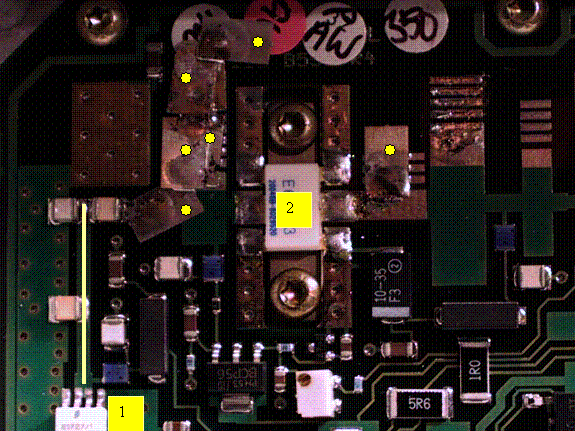
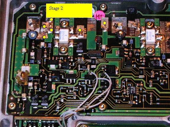
Second amplifier stage, common to all stripline versions.
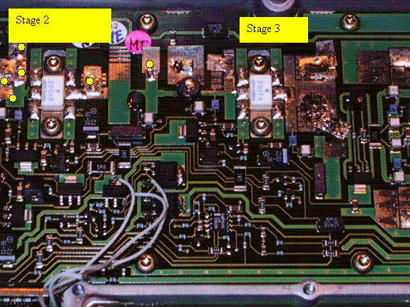
Third amplifier stage, stripline dependent.
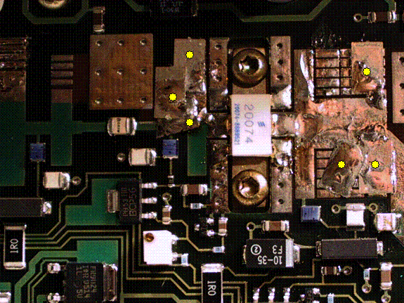
Fourth parallel amplifier stage, stripline dependent.
4) Apply 10-20mW RF input and commence final fine-tuning of the two built-in trimmer capacitors, try to balance the output between the two transistors.
Final word
The positions of the copperî flagsî have been successful most of the
time, however ñ there are probably many possible small changes that can
be made to gain a few extra watts or so. Remember that an individual
flag in the right place will add a fraction of a watt, so the final
result is a product of many small copper flags positioned in the right
spot.
Good Luck!.