| Amateur Radio
Satellite Ground Station
Satellites
that can be used
From SK0CT
satellite station you can manage two-way FM, CW or SSB contacts
using any of the following analogue satellites:
VO-52, AO-51, SO-50. AO-07, FO-29, ARISS
The following satellites
have previously been used, although some satellites are non-operational
today.
AO-10 & UO-14 & RS12/13 & RS-15 & FO-20 & AO-07
& FO-29 & AO-27
For an update on available satellites, see
Swedish Amsat organization: Amsat.se
Using the
satellite station
The Yaesu transciever is fully pre-programmed with the analogue satellites,
up and down -link frequencies and used sub-tones. Once in "satellite mode" simply
select satellite on the LCD menu.
The satellite
tracking system, once started, is fully automatic.
Kepler-update can be done via the tracing SW control menu.
Technical
information/setup
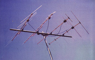
ANTENNAS
VÂrgÂrda "Satellite" Array, 2x6 el on 145Mhz and 2x13
el on 435Mhz
Circular polarization
<
ROTATOR
Combined Azimuth and Elevation rotator G-5500
Manual or automatic tracking
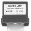
PREAMPLIFIERS
SSB Electronics SuperAMP Preamplifiers SP-2000
(145Mhz) SP-7000 (435Mhz)
Manual T/R control, adjustable gain

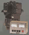
CONTROL
Primesat, PIC based Rotator Controller with LCD
 
COMPUTER POWER
Pentium 4 (3GHz) with WindowsXP SP1
SOFTWARE
Orbitron tracking software
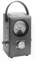
Reflected / Power Meters
Bird Power/SWR meter used both on 145 and 435Mhz

TRANSCEIVER
Yaesu FT-847, dual band, all mode transceiver
with dedicated satellite functions
Operating
the SK0CT satellite station
The satellite station is operational once the FT-847 transceiver, computer
and satellite rotator is switched on. The FT-847 is prepared with the
required settings for all the listed individual satellites. Just push the
ìSATî button on the transceiver to gain access to the preprogrammed
memories with satellites. On the computer, double-click on the Orbitron desktop, then select PrimeSat in the Orbitron
rotator control meny. As a result the Primesat menu pops-up automatically and then select
ìrotator control ONî. Now it is possible to select a satellite by
double-click on one of the satellites visible in the Orbitron
map.
At this stage, automatic satellite tracking is done, to change satellite,
just double click on the required satellite.
Due to the coaxial cabling at the antenna the maximum elevation is
restricted by setting in Orbitron.
NOTE:
Before transmitting make sure that the
duplex/Mode-JA filter switch is set to the correct position. The Mode-JA
filter must be disabled when other satellites than FO-29 are operated.
Due to the narrow characteristics of the filter, high mismatch (SWR) could
damage the VHF/UHF Transceiver.
The filter is enabled/disabled using the small switch located abouve the FT-847 transceiver.
Mode JA
Filter
The mode JA filter is
used to enhance the performance of the 435Mhz downlink on FO-29 from being
less disturbed from interference generated by the 145MHz uplink
signal and to suppress any interference with the SK0CT/R repeater on RU1
(434.625Mhz output / 436.225MHz input).
When this filter is connected it enables you to simultaneously receive
signals from the satellite downlink while transmitting on the
satellite uplink.
Filter
Data
The custom designed
Mode JA FO-29 satellite filter is made of†
four separate coaxial cavities (2+2pole) on the 70cm band and
additional two º -wave coaxial cable stubs (2pole) for suppression of the
3'd overtone generated by the 2m band.
The 435Mhz downlink
signal first arrives from the antenna/pre-amplifiers down to the pair of
º-wave stubs. The stubs suppresses the 145Mhz 3'd overtone by approx.
-70dB. The 3'd overtone is generated by the satellite Mode-JA uplink
carrier on 145Mhz. (145.8Mhz x 3 = 437.4MHz).
Once the 435MHz
downlink signal has passed these coaxial stubs, the signal is fed further
into the coaxial cavities. The attenuation outside the 435MHz passband is -40 to -54dB.
Passband: 435.800MHz - 436.000Mhz.
The total attenuation within the passband, is -1 to 1.5dB.
RU1 SK0CT/R:
Repeater input: 436.226Mhz -54dB attenuation in the filter
Repeater output: 434.625Mhz -40dB attenuation in the filter
Special thanks to:
Filter specifications and time: Christer SM5WFD
Filter HW: donated by VRK, SK5AA
|