Modification of a 30W 2,1GHz driver for 2,3GHz
Modification of a 30W 2,1GHz driver for 2,3GHz
Typical data on 2,3GHz after
modification :
Gain: about 40dB, Output power
30-40W
Active device: Motorola MRF 21030, VDD 28V at 5A
Two MRF21030 are
used in the final stage of this drive originally made for linear operation on 2,1GHz. To make it
operate on 2,3GHz, all you need to do is some adjustment on two variable
capacitors. Although the power is a modest 30-40W, there is still
a need for a good heat sink.
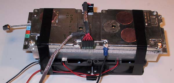
On the sample shown here, two computer grade fans are used to cool
the heat sink. They are really needed, one fan was not enough. While on
the subject of the heat sink, make sure that slots are provided to
accommodate the transistors in the heat sink. It is essential that the
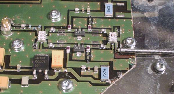
PCB is absolutely flush with the heat sink. To provide a sufficient
ground pad for the
coax braid, remove the green solder mask near the screw, as shown on the
picture below. The centre conductor of the coax is connected
to the trace leading to the input hybrid coupler.
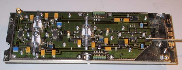
The signal is split in two MMICs and recombined to feed a
single MRF21030 that in turn is split in a hybrid, feeding two MRF21030
that are recombined to the output SMA female connector. Two adjustable
capacitors on the PCB are the only easily accessible trimming points.
There are pads provided at the output of the final transistors for
squeezing the last W out of the driver. However in this unit no attempt
was made to further increase the gain or output power, as the available
40W is more than enough for the purpose to serve as a driver stage.
Bias is +28V that is brought down to +12V provided by two build in regulators,
via an adjustable resistor for each power LDMOS respectively. To provide
a PTT line, a relay or similar can remove the +28V bias line. The idle
current will then go to zero without need to remove the VDD when PTT is
in RX. Please note, there are two connections strips for the bias and
VDD,one on each side of the PCB.